Monday, December 22, 2025

Bi-Color Cyanotype Experiments

I was recently inspired by bi-color cyanotypes I saw online, and wanted to take a crack at the process myself. I started simply with solid colors rather than printing with negatives, as the testing process would probably be very long for the latter. I first wanted to see what this process is capable of.

Since I'm sure everyone is familiar with how cyanotypes are made, I won't describe the process in detail. The yellow layer in bi-color cyanotypes come from bleaching a blue cyanotype with sodium carbonate (washing soda). I use 1 tsp sodium carbonate to 1 L hot water, and bleach the cyanotype to completion. My first tests were to determine how much exposure was needed to achieve a satisfactorily yellow layer.

I expose my cyanotypes using a DIY exposure box, lined with UV LED strips. The UV intensity in this box is rather low, so my exposure times tend to be longer. However, I can achieve much greater consistency using my exposure box than relying on sunlight.


From left to right, the exposure times are 30m, 60m, and 90m. Not a huge difference between the three prints at this stage.


The same prints, but fully bleached with sodium carbonate. Despite the initial prints having very similar values of blue, here it's apparent that the overall exposure during the blue step makes a big difference in the yellow value.


On each bleached print I coated another cyanotype layer and exposed all three for 30 minutes. I reduced this exposure time for later prints, but it's still easy to see that the darkest yellow combines best with the blue layer to make green. The fact that the blue and green aren't too different in value makes the prints feel a little flat.

Here is a later print that I'm happy with, with the blue layer receiving less exposure than the prints above. The exposure may have been on the light side, but the color separation is much cleaner:


I have more experiments I'd like to attempt with this technique, so stay tuned for more soon.

Thursday, December 11, 2025

Rule of Thirds Gauge

We're all familiar with the rule of thirds, and how we can use it when composing a shot or in the darkroom to elevate a photograph to a masterpiece. I've been finding it very tedious having to measure thirds in the darkroom with a ruler, or cutting appropriately-sized pieces of paper with lines drawn to mark the thirds. I've found an elegant solution to this problem that is both easy to DIY and is adaptable to all sizes of paper.

Inspired by the golden ratio gauges often constructed and used by woodworkers, I took pen to paper to conceptualize what a similar gauge would look like when constructed to give three equal sections. Here are my initial scribblings:

A quick sketch lays out the unit lengths for each arm of
the gauge. Three units for each long arm, two units for
the short arms.

The idea was simple enough, and to my surprise, it was even easier to construct a functional prototype. I sort of brute-forced the solution with super simple math, working with a unit length of 9cm. I'm sure there is a mathematical proof that shows why this device works, but I'm happy enough having sorted it out so simply. The two long arms are 27mm from the pivot point to the tip, and the two short arms are 18mm from their pivots to the tip. All pivot points are 9cm apart. These lengths can of course be adjusted for any sized gauge you wish to construct, as long as the ratios stay the same. Here is a photo of my prototype, made of cardboard and complete with toothpicks to hold everything together:

The gauge functions by first adjusting the two outer points to the desired dimension. When set, the two inner points will show the exact lines that divide the paper into three sections. Easy thirds, without a ruler!

For the final product, I took some black matboard and cut it into 1" strips. I drilled holes with the four pieces clamped together so the holes would be exactly the same on all pieces. The ends were cut to points, and brass brads were used to hold the whole contraption together.

Simplicity, ease of construction, and versatility, this gauge has it all. So far it's proven to be extremely valuable in the darkroom, and I hope to see others start using this tool as well!

Monday, December 1, 2025

Exposure Considerations for the Holga Wide Pinhole Camera (120WPC)

I love the Holga 120WPC. It's lightweight, easy to use, and can yield awesome results in 6x9 or 6x12 formats. It does however have a significant drawback, which is related to focal length and negative size. The physical focal length (the perpendicular line from the pinhole to the film plane) of this camera is approx. 40mm, but with the 6x12 mask in place the edges of the negative are much farther away from the pinhole than 40mm. I'll illustrate:


The labeled f-stop on the 120WPC is f/135, but as I've shown in my calculation above, the effective f-stop at the edges of a 6x12 negative is f/240. This gives an approximate exposure difference of two stops from the center to the edge. This is a noticeable difference, perhaps not for those who are scanning film, but indeed so for those of us who print in the darkroom. 

Interestingly, this 2-stop exposure difference is retained, regardless of exposure length. Using the exposure suggestions on the back of the 120WPC, I assigned Exposure Values (EV) to each and made exposure calculations, correcting for reciprocity failure where needed:

The recommended exposure times on the
back of the Holga. I assign EV 15, 13,
and 11 to these weather descriptions.


Even when accounting for reciprocity failure (in this case, using P=1.15 for TMax100 film), the adjusted exposure for the edges of the film is approximately 4 times (2 stops) greater than at the center. It's nice knowing that we don't need to make more complex calculation on-scene when using this camera.

With these calculations in mind, we can strategize when using his camera, to either use this shortcoming to our advantage, or selectively place bright subjects off-center so they don't wind up unnecessarily over-exposed. I'll show some example photos of mine below, and caption them with some discussion and explanation.

This photo is scanned from a darkroom print. I slightly dodged the edges to lighten them a bit, but they are still much darker than the middle. In this case, with the sun shining through the trees in the middle, I like the effect and don't mind the dark sides.

A scanned negative. Again, a bright subject placed centered in the frame gets extra exposure and is exaggerated. I think this characteristic of the camera works to great effect here.


Other considerations when shooting with this camera include keeping track of light sources. In most cases, having the light source behind the camera gives the best chance of success. Sometimes though, having the sun in-frame can yield interesting results:

A unique artefact of the suns light interacting with the pinhole. Not a bad effect; I was pleasantly surprised seeing this come out of the development tank. This photo is a scanned negative.

On the other hand, sometimes the sun will accidentally shine through a scene, creating unintentional and undesirable flare on the film:

Here, the sun is obviously out-of-frame, but it was shining onto the pinhole nonetheless. The resulting flare spoils the photo for me, so this negative isn't likely to see any action in the darkroom.

In my experience, the only way to be completely sure to avoid these light flares, is to point the camera completely away from strong light sources. I may try modifying a hood that could fit on the camera someday.

I hope this deep dive into the nuances of the 120WPC was of interest! As always, I encourage discussion and very much welcome feedback.

Tuesday, November 4, 2025

Test Procedure for Enlarging Lenses using Vlad's Test Target

Some of you may have read my previous blog post about comparing the performance of five 50mm enlarging lenses. I'm proud of the work I put into that post, but I wanted to develop a more standardized way of testing enlarging lenses without necessarily having multiple lenses of the same focal length.

In comes Vlad's Test Target (link to his website), a fine-grain mounted negative designed to calibrate camera-scanning rigs. I stumbled upon his product online, and immediately saw how useful it could be in the darkroom to test lens resolution and center-to-corner performance. The test slide is made with Adox CMS Pro II film and has an official resolution of 110 line pairs per millimeter (lp/mm). Details this fine rival the resolution achievable on fine-grain films such as Kodak TMax1001 and Ilford Delta 100. Adox CMS Pro II is incredibly fine-grained and is capable of resolving up to 800 lines per millimeter (l/mm), so the limitation of the film stock itself will have no effect on this experiment. The design and principle behind the test pattern can be found here. As of now I only have the 35mm version of this slide, which I don't plan to use to test lenses longer than 80mm (Vlad makes test targets in larger sizes).

Vlad graciously provided me with this high-quality scan from his test slide, which shows the test lines alongside their corresponding resolution in lp/mm. Note how small this area is on the slide itself (1.5 x 1.3mm); it can be viewed in some of my test prints below. The slide was scanned by Dominique Ventzke at High End Scans.


To prevent this post from getting too lengthy, I focused on testing only two lenses that in my opinion are on opposite ends of the quality spectrum: the EL-Nikkor 50mm f/2.8 and the EL-Omegar 50mm f/3.5. My hope in testing these particular lenses was that I would see similar results in center sharpness but noticeably different results in the corners. The EL-Nikkor was tested at print sizes of 5x7, 8x10, and 16x20. The EL-Omegar was only tested at 16x20, to most clearly illustrate the difference between the two lenses. I did not print full sheets at each of these sizes (only for the 5x7), but rather adjusted the enlarger to the proper size, and printed a small area of the test slide that contained the area I wanted to analyze. I made all prints at f/8, both to simplify the procedure and to give the lenses their shot at the most "ideal" printing aperture.

Each of the resulting prints was scanned at 1200dpi on a flatbed scanner. At this resolution, the test target and the lenses being used are the limiting factor rather than the resolving capability of the scanner.

5x7 print of the test slide using EL-Nikkor 50mm at f/8.

The 5x7 print was, as expected, very sharp and the details were all excellently resolved. I wasn't expecting to push any limits at this size, just needed a straight print. The corner details appear to be exactly as sharp as the details in the center. When I zoom into the scanned print, I can see slight differences in sharpness, but the difference is indiscernible to the naked eye.

    
Enlarged now to 8x10, much finer details can be seen. The smallest lp/mm are more discernible, but not yet fully resolved.


At 16x20, my enlarger has reached its maximum height without having to adjust it to project onto the floor. The very smallest details are visible now, and the resolution limit of the test target has been reached. The corners are quite obviously softer than the center, but still very suitable for printing.


And here are the results from the EL-Omegar. In my last discussion on this lens, it mainly showed inconsistencies between aperture settings and overall poor sharpness at all but the most ideal apertures. These prints reveal another interesting characteristic of this lens, particularly in the corners. The center is arguably as sharp as that of the EL-Nikkor, especially at f/8, which is expected to be the sharpest. What was interesting was the distortion that can be seen in the corners. The test lines that are tangential to the lens appear decent, but significant blurring can be seen in the radial lines.

Cropped in from the previous photo; the difference
between radial and tangential lines is very obvious.

I'm no optical engineer, but I can only assume the effect we see here is a factor of lens design, and not of anything about my setup. I would always expect a lens to lose some sharpness in the corners, but this is almost beyond usable. The distortion blurs details in the 15-17 lp/mm range, which would considerably reduce resolution when printing even the grainiest films.

In conclusion, I'm very satisfied with the results I was able to obtain with Vlad's Test Target. It is a quality product, perfectly suited for darkroom use, and highly recommended by me. I believe the results I obtained are very clear and the differences between these two lenses thoroughly demonstrated. I always welcome feedback of any kind, and hope that this post is of some use to those reading it!

Thank you.


1. The official datasheet for TMax100 lists a resolution of 200 lines/mm. Converting to line pairs per mm gives 100 lp/mm, barely less than the resolution limit of the test target.

Friday, August 29, 2025

How to Develop Found Film

I'm frequently searching thrift stores and camera shops for old equipment, and occasionally I'll find a camera with an exposed roll still inside. The packaging reveals the type of film and usually the development process needed (in the case of color films). But long-expired films are often fogged or the development process is obsolete. I'd like to share how I process found film at home and get consistent results.

My development process is very simple, and uses HC-110 developer:

  • 1+90 dilution HC-110
  • 18 minutes development
  • Agitate for the first 30s, then for 10 seconds every 3 minutes thereafter

This development will work for old color films, but naturally will result in low-contrast B&W images. Many color development processes have been replaced with modern processes (for example E-6 has replaced E-3 and E-4), so white attempts with modern color chemistry could be employed, the method described above is a cheap and quick way to get results.

Once developed, scanning the negatives can be tricky, especially if they are severely fogged. I scan using an Epson V500, and following a preview scan will adjust the brightness and contrast until I can obtain a decent image. Below are come comparison images to show the condition of the negatives, and the best result I was able to get while scanning:


You can see that the negative here is in somewhat bad shape, but for film that was developed after 60 years, the result is actually quite nice!

This example is likely from the 80s, so while the film had fogged somewhat, the latent image was still in good shape and the film base hadn't been exposed to fungus or moisture.


Here you can see what good scanning is capable of. On the left above you see a cellphone photo of the negative, with an incredibly faint image. On the right, my final scan after manipulating settings in the scanning software. The film was in bad shape, but the result is still decent!

A particularly bad example, from
the same roll as the last photo
.
The subject can still

be identified though!


Wednesday, August 13, 2025

Developing 116 Film in a Paterson Tank

I recently found an exposed roll of 116 film in an Ansco Buster Brown 2A camera. 116 film has been out of production for quite a while, and resources for developing this size of film is very limited these days. I'm showing here how I was successfully able to develop a roll of 116 film at home with modern Paterson film developing equipment.

Here is a picture of all the materials I used to set up the reel. The important pieces are a single complete Paterson reel (pictured on the right) and a small half from another Paterson reel (the half that fits snugly onto the center tube):

The key to the function of this setup is the half  reel nestled into the top half of the main reel. This keeps things concentric, and without it, the larger diameter half of the reel would be loose and wouldn't hold film.


The extra half reel is placed backwards onto the larger half of the full reel, such that everything sits well-aligned on the center tube. Here's the final arrangement assembled on the center tube.


And here is how it looks with 116 film inserted onto the reel. I was fortunate that this was orthochromatic film, so I could load it under safelight. The trickiest part was making sure the pieces of the reel don't slide apart, since in this configuration they aren't locked together:


I hope whoever stumbles upon this post find this info useful!


Monday, March 24, 2025

Enlarging Lenses & Ideal Printing Apertures?

General advice in various darkroom-focused groups on the internet tells us to only use the "middle" aperture of an enlarging lens, or alternately 3 stops down from wide open. It certainly is good advice, but how rooted in empiricism is it? What exactly do we sacrifice when we adjust up or down one f-stop? What about adjusting 2 f-stops? My goal in this post is to provide some discrete examples of those effects, as well as to compare the overall performance of some well-known enlarging lenses.

I compared 5 enlarging lenses, all of which have a 50mm focal length. They differ somewhat in aperture ranges, but I will describe them further below and explain my testing process. The lenses I tested are:

  1. Schneider-Kreuznach Componar f/3.5
  2. Schneider-Kreuznach Componon f/4 
  3. Nippon Kogaku EL-Nikkor f/2.8
  4. Fuji Fujinar-E f/4.5
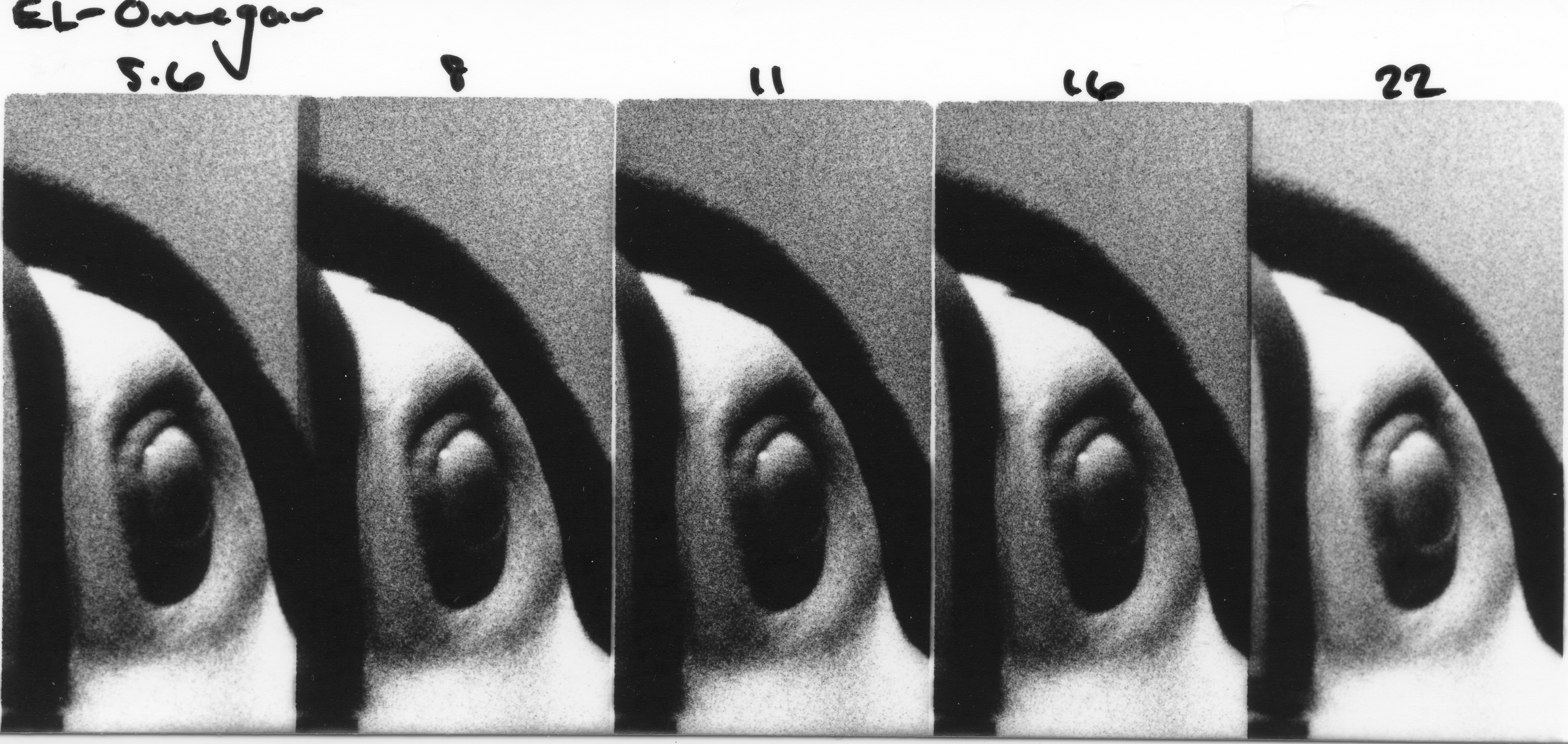
  5. Omega EL-Omegar f/3.5

Some of these lenses have impractically open apertures when used wide-open (looking at the EL-Nikkor f/2.8 in particular), therefore I tested the 5 smallest apertures on each lens, since these are the ones that will likely see the most use.

The negative I decided to enlarge for this test was a recent shot of a toucan at the zoo. I was pushing Kodak 5222 Double-X to 1600 just to see what kind of results I could get. The photo is deliciously grainy, a quality I was looking for in this series of tests because the sharpness of the individual grains will be more evident at different f-stops than the sharpness of the subject or overall image. I made a cropped 5x7 test print of the negative; the exposure was 32 seconds at f/11 using the Fujinar-E lens listed above. The projected image was approx. 10"x12", and I used a #2 Ilford contrast filter.

Testing Process

For my test strips, I cropped even further to include just the area around the toucan's eye and a bit of the blurred background. I focused all lenses at their most open aperture, and stopped down to make 5 different exposures per test strip, one exposure per aperture. I've labeled the apertures on each of the scanned test strips below, and I'll discuss the performance of each lens below the test strip.

Exposure times were extrapolated from the 32 seconds required for the test print and were used for all lenses:

f/4 - 4 seconds

f/5.6 - 8 seconds

f/8 - 16 seconds

f/11 - 32 seconds

f/16 - 64 seconds

f/22 - 128 seconds


Schneider enlarging lenses have a good reputation, and for very good reason. Each successive stop down, and therefore doubling of exposure time, is very consistent along the tested range. f/4 is a little bit soft, but the grains are sharper at f/5.6 and fully sharp at f/8 up to the smallest aperture of f/16.


Similar to the Componar above, the Componon performed excellently. Brilliant consistency across the aperture range, and very sharp from f/5.6-f/16. Not much else to say, it's quite obvious why Componon lenses are some of the most recommended.


The EL-Nikkor performed just about as well as the Componon. Very consistent, and also very sharp from f/5.6 and smaller. Perhaps at f/16 it appears slightly less sharp.


I made a small mistake with this test strip. I forgot to stop down to f/22 for the last frame, and with that requiring an additional 2-minute exposure, I decided to forgo making an entirely fresh test strip. Similar to the performance of the lenses above, the Fujinar is quite consistent in exposure time as it is stopped down, with a bit of softness wide-open. Apertures f/8-16 all seem useable.


Perhaps not surprisingly, the EL-Omegar performed quite poorly. The exposures on the test strip varied considerably, meaning that adjusting this lens up or down a stop does not give an equal exposure by halving or doubling the exposure time, respectively. The lens is at least reasonably sharp around the middle apertures, f/11 is certainly an acceptable exposure if this is the only lens available.


Conclusion

In conclusion, it would seem that the extreme apertures of most enlarging lenses are either sub-optimal in terms of image quality, or impractical in terms of required exposure time. The middle apertures of all the lenses produced acceptable results, and I think are very difficult to differentiate when analyzing prints. Choosing quality lenses will make adjusting exposure when stopping up or down easier, but it seems we have a lot more room to play with than initially thought!

Thursday, January 23, 2025

Color Control in Sepia Toning

I love sepia toning my prints, not only because it's an archival toning method but also because it can add very subtle color effects to enhance a print. I've been playing around with the level of color control that can be achieved and I'd like to share my results here.

I'd like to acknowledge some sources that were very helpful in learning the intricacies of sepia toning.

I won't be discussing the preparation of stock solutions or toning process, as all of the resources above as well as countless other books and websites have that information readily available. This experiment uses Thiourea (Thiocarbamide) sepia toning solution, therefore the results will not be applicable to other types of toning solutions.

My first round of calculated mixing ratios, from 9+1 to 1+9.

Here are the results of the first sepia toning experiment, where I used the extreme ends of the mixing ratios to see what effect I'd get. These prints were all produced one after the other on Ilford MGRC Pearl paper. Resin-coated paper is difficult to tone, so the bleaching time was quite long on these. I do think the toned prints do give a good sense of the color variation possible. Below the toned prints is the original print. Click on any of the images to enlarge them.


Thiourea : NaOH

9+1           7+3           5+5           3+7           1+9


For the next test on fiber-based paper rather than splitting the toning ratios into 10 parts, for the sake of making measurements easier I decided to try splitting them into 5 parts. This made my ratios a bit simpler but less extreme: 3+3 being a neutral sepia, and the extremes at only 5+1.

My revised and final calculated mixing ratios.

This next set of prints was printed on expired Agfa Brovira Grade 3 Semi-Gloss paper, probably from sometime in the 1980s. This paper has been fun to use, and although it needs extended exposure times I've still gotten great results from it. The subject is a small section of a picture I took of gingko leaves; the final print that has since sold was sepia toned yellow to match the yellow color of the original gingko leaves.


Thiourea : NaOH

5+1            4+2            3+3            2+4            1+5


The fiber-based paper was much easier to bleach, therefore the toning color is much more obvious in the shadows and overall the color is much more rich. I don't usually bleach my prints to completion but since this is an experiment in toning, I let the prints go for about 5 minutes each until only the darkest shadows still remained. 

In a scenario where I'm producing an art print, I'll decide ahead of time what color I want to use and only bleach the print up to the point where I want to show the colors. In most cases this will mean bleaching the highlights but leaving the darker midtones and shadows unbleached. This gives a great mix of sepia color and rich shadows, which makes the prints much more 3-dimensional than a full bleach and tone.

In conclusion, I'm happy that I was able to show big differences in color when controlling the ratios of Thiourea and Sodium Hydroxide in sepia toning solutions. I think that working with the reduced ratio range (5 different mixes) gives most easily measured volumes and enough color control to fit most scenarios.


Thanks for reading! If you're interested in seeing more of my photography, please check out my Linktree.

Bi-Color Cyanotype Experiments

I was recently inspired by bi-color cyanotypes I saw online, and wanted to take a crack at the process myself. I started simply with solid c...